
GM SUV Adjustable Trailing Arms Installation Guide | Tahoe, Yukon, Escalade
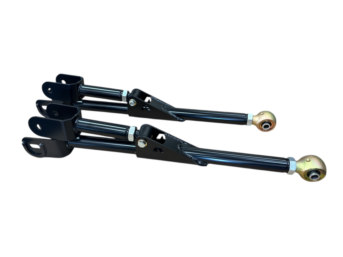
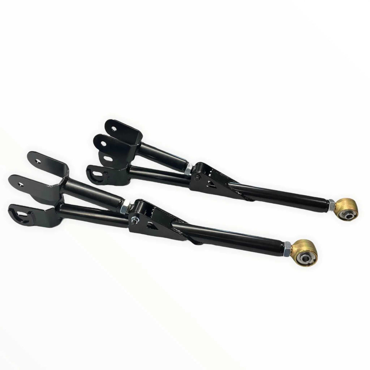
GM SUV Adjustable Trailing Arms
Installation Guide | Apoc Industries | Part Number: AP-900-401
Fits: 1999–2019 Chevrolet Tahoe, Suburban | GMC Yukon, Yukon XL | Cadillac Escalade
865-983-5004 | 9–5 EST | support@apocindustries.com
Kit Includes
- (2) Upper trailing arms — notched for brake caliper bolt clearance
- (2) Lower trailing arms
- Polyurethane bushings with grease fittings
Optional Hardware Kit (if ordered)
- 4 x M14-2.0 x 80mm bolts — upper arms
- 4 x M14-2.0 x 100mm bolts — lower arms
- Lock nuts and washers
If the optional hardware kit was not ordered, factory hardware will be reused.
Safety
Before starting, ensure safety by parking the vehicle on level ground and placing wheel chocks on the front wheels to prevent rolling. Always wear safety glasses and use the correct tools.
Required Tools
- Floor jack and jack stands
- Torque wrench
- Socket set — metric
- Grease gun
- Magnetic angle finder or digital inclinometer (for pinion angle verification)
- Wheel chocks
- Safety glasses and gloves
Arm Length Chart
All measurements are center-to-center from one bolt hole to the center of the adjacent bolt hole. Set arms to the correct length before installation. Apply red Loctite to the jam nuts once set to the proper length to prevent loosening over time.
| Drop Height | Upper Arm | Lower Arm |
|---|---|---|
| Stock | 17 1/4" | 21 7/8" |
| 2" Rear Drop | 17 1/8" | 21 15/16" |
| 3" Rear Drop | 17 1/8" | 22 1/16" |
| 4" Rear Drop | 17 1/4" | 22 1/4" |
| 5" Rear Drop | 17 3/8" | 22 7/16" |
| 6" Rear Drop | 17 9/16" | 22 5/8" |
| 7" Rear Drop | 17 7/8" | 22 15/16" |
⚠ Important Note: Drop Brackets
If you have drop brackets installed that relocate the trailing arm mounting point on the frame, the arm lengths in the chart above are not correct for your application and should not be used directly.
Drop brackets can move the mounting hole in more than one direction — not just vertically, but also forward or rearward to help re-center the axle in the wheel well. Both dimensions must be accounted for when determining the correct arm length.
To find your correct starting arm length:
- Measure center-to-center from the factory frame hole to the drop bracket hole — measure both the vertical offset (up/down) and the horizontal offset (forward/rearward) separately
- Your actual rear drop amount minus the drop bracket’s vertical offset gives you an approximate starting point. For example, if you have a 4" rear drop and the bracket moves the mount 2" vertically, use the 2" drop row in the chart as your starting point — because the bracket has already accounted for 2" of that geometry change
- Then account for the horizontal offset: if the bracket also moves the mount rearward (toward the axle), subtract that amount from your arm length. If it moves the mount forward (away from the axle), add that amount
- Example: 4" rear drop, bracket moves mount 2" down and 1/4" rearward — start with the 2" drop arm lengths from the chart, then subtract 1/4" from those measurements
- Fine-tune from there based on your measured pinion angle and axle centering at ride height
When in doubt, verify pinion angle and axle position after installation and adjust arm lengths as needed before final torque.
Torque Specifications
| Fastener | Torque (ft-lbs) |
|---|---|
| Trailing arm bolts — upper & lower | 136 ft-lbs |
| Shock bolt | 97 ft-lbs |
⚠ Always torque all trailing arm bolts with the vehicle at ride height — full weight on the suspension. Torquing with the suspension hanging will preload the bushings and cause premature wear.
Installation Steps
Step 1 — Prepare the Vehicle
Park on a level surface and set the parking brake. Place wheel chocks on the front wheels. Loosen the rear lug nuts slightly before lifting the vehicle.
Step 2 — Raise the Rear and Support on Jack Stands
Using a floor jack, raise the vehicle’s rear by the axle housing until the vehicle’s weight is off the tires. Place jack stands under the frame in front of the rear axle on both sides. Keep the floor jack under the axle so you can raise and lower it during installation.
Step 3 — Relieve Shock and Coil Spring Pressure
Loosen the lower shock bolts on both sides. Lower the floor jack slowly to relieve weight on the coil springs until the lower shock bolt turns easily. Remove the shock bolts and lower the axle until the weight is off the coil springs.
Step 4 — Set Arm Lengths
Before removing the factory arms, set the new Apoc adjustable trailing arms to the correct center-to-center length for your drop height using the chart above. Apply red Loctite to the jam nuts once set to prevent loosening over time. Setting the lengths on the bench is much easier than under the vehicle.
Step 5 — Remove Factory Trailing Arms and Install New Arms
Remove all upper and lower factory trailing arms. Important: With all trailing arms removed, the axle is no longer supported and the pinion can rotate up or down freely. The axle will also want to roll forward without the arms holding it in place. Use a jack stand or additional floor jack to support the axle and control its position while removing the arm bolts to prevent binding. Install the new Apoc trailing arms in their place — installing the uppers first is usually easier. Thread all bolts by hand but do not torque yet.
Step 6 — Upper Arm Brake Caliper Clearance Check
Once the upper arms are installed, verify that the upper arm clears the brake caliper bolt. The upper arms are notched specifically for this clearance — confirm fitment before proceeding.
Step 7 — Reinstall Shocks
Raise the axle with the floor jack to compress the coil springs back to ride position. Reinstall the shock bolts but do not fully torque yet — leave loose until the vehicle is at ride height.
Step 8 — Reinstall Wheels and Lower to Ride Height
Reinstall the rear wheels and hand-tighten the lug nuts. Remove the jack stands and lower the vehicle to the ground so the full weight is on the suspension. Roll the vehicle forward and back a few feet to allow the suspension to settle at true ride height.
Step 9 — Final Torque
With the vehicle at ride height and full weight on the suspension, torque all fasteners to spec:
- Trailing arm bolts (upper & lower): 136 ft-lbs
- Shock bolt: 97 ft-lbs
- Lug nuts: Factory spec — refer to owner’s manual, in a star pattern
Step 10 — Grease All Bushings
Using a grease gun, pump grease into all bushing grease fittings on both upper and lower arms. We recommend a high-quality grease such as Lucas Red “n” Tacky. A few pumps per bushing is sufficient — stop when grease begins to appear at the bushing edges.
Step 11 — Final Inspection
Verify that nothing is rubbing, that brake hoses and ABS sensor wires are not pinched or stretched, and that all hardware is properly torqued before driving.
Understanding Pinion Angle
Why Pinion Angle Matters
Most solid-axle trucks leave the factory with approximately 1–3 degrees of nose-down pinion angle at static ride height. This small downward angle is intentional: under acceleration, axle wrap causes the pinion to rise slightly, bringing the U-joint operating angles closer to parallel — which is the ideal operating condition. The goal is to keep the operating angle at each U-joint in the 1–3 degree range when the vehicle is sitting at normal ride height under its own weight.
When you lower a vehicle, the driveshaft angle changes. Adjustable trailing arms allow you to correct pinion angle so your driveline stays within the proper operating range, preventing vibration, premature U-joint wear, and driveshaft failure.
How to Measure Pinion Angle
- Measure with the vehicle on level ground at normal ride height — full weight on the suspension, gas tank reasonably full, no extra load
- Use a magnetic angle finder or digital inclinometer
- Measure the angle of the driveshaft
- Measure the angle of the pinion flange — place the tool on the flat face of the pinion yoke
- The difference between these two measurements is your true pinion angle
- Nose-down = positive number in standard shop language — the pinion is lower than the driveshaft centerline
- Target: 1–3 degrees nose-down at static ride height
Fine-tune the arm lengths equally on both sides to dial in the correct pinion angle after your initial installation. A professional driveline shop can verify your angles if needed.
Post-Installation Instructions
- After driving for 500 miles, re-torque all fasteners and inspect all components visually.
- Have the vehicle aligned after installation — lowering changes suspension geometry and affects alignment.
- Grease all bushing fittings at each oil change interval.
- Before driving, visually inspect all components to ensure they are functioning properly.
Safety Disclaimer
This installation guide is provided for reference purposes. Apoc Industries assumes no liability for improper installation, use of incorrect torque values, or failure to follow all safety procedures. Suspension modifications significantly affect vehicle handling characteristics. Always have suspension work inspected by a qualified mechanic and comply with all local laws regarding vehicle modifications.
Apoc Industries | apocindustries.com | 865-983-5004 | support@apocindustries.com | Document Version: v1.0

865-983-5004
Customer Service
Phone support available 9 AM–5 PM EST, Monday–Friday. Call us with questions or leave a message in the chat box—we'll respond during business hours.
Blog posts
Why 2014-2026 Ram 2500 Trucks Need Adjustable Radius Arms After a Lift
How adjustable radius arms help 2014–2026 Ram 2500 trucks control axle position, caster, and front-suspension articulation from stock height through a 10-inch lift.
Why 2005-2022 Ford Super Duty Trucks Need Adjustable Radius Arms After a Lift
A practical look at how lifting a 2005–2022 Ford Super Duty changes front-end geometry, and how adjustable radius arms and flex joints help restore control on the road and articulation off-road.

Tire & Wheel Fitment Guide: 2014-2026 Ram 2500/3500 with a Leveling Kit
Running a leveling kit on your 2014-2026 Ram 2500 or 3500? Here's exactly what tire and wheel specs you need for a clean, no-rub fit — including Ram-specific offset and track bar tips.